NUEDC

Award
Awarded the second prize in Beijing (ranked second within Beijing).

Problem Statement
Design and develop an internet-based camera measurement system as illustrated in the figure below. The system consists of a square area with a side length of 1 meter, with three vertices labeled A, B, and O. There are two independent camera nodes placed at A and B, capturing images along the AO and BO directions as orthogonally as possible. These two camera nodes are connected via a 100 Mbps/1 Gbps Ethernet switch to a terminal node for network communication. The switch must be a standard internet-compatible switch, and the network ports can be specified freely. A laser pointer, suspended by a flexible transparent string of length l, hangs above point O, with the pointer always on and pointing downward. When at rest, the laser spot coincides with point O. The laser pointer can be pulled away from its rest position by less than 10 cm, and upon release, it swings freely. The trajectory of the laser spot passes through point O in a straight line, forming an angle θ with the edge OA. The system should measure the string length l and the angle θ.
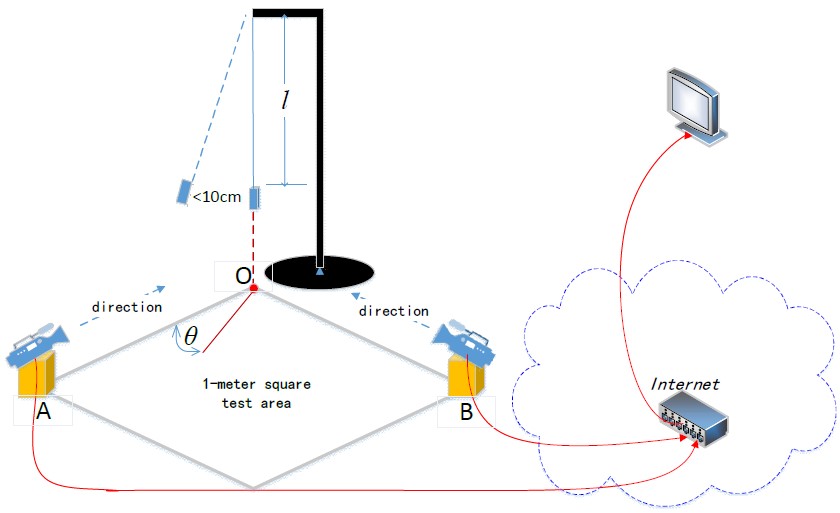
For more detailed information about the problem, you can refer to the original Chinese document here.
Proposed Solution
Abstract
We designed and developed an internet-based imaging measurement system using Raspberry Pi and a gigabit switch. The system identifies a laser pointer performing simple pendulum motion and measures the pendulum’s string length and the angle between its ground projection and a boundary. Two imaging nodes, each consisting of a Raspberry Pi and a camera, capture the laser pointer’s movement. The data is transmitted through a gigabit switch to a terminal node, also built with a Raspberry Pi, which processes the images using image recognition techniques to calculate the string length and angle. The results are displayed on a screen. The system was optimized for accuracy, speed, and algorithmic complexity. After analysis, design, software development, and testing, the system met the expected design requirements.
Calculation
Two cameras capture images from the 0° and 90° directions, recording the pendulum’s motion projected onto the xOz and yOz planes. Using OpenCV, the laser pointer’s position can be identified in the images, and the central coordinates can be determined. By analyzing the motion period and the lateral range of the trajectory of these coordinates, the string length and angle can be calculated.
Calculation of String Length L
The formula for the period of a simple pendulum is given by:
$$ T = 2\pi \sqrt{\frac{L}{g}} , $$where g is the gravitational acceleration, and L is the distance from the pendulum’s center of mass to point \(O\).
In the problem statement, with $50\, \text{cm} \leq L \leq 150\, \text{cm}$ , the corresponding period range is $0.448\, \text{s} \leq T \leq 0.777\, \text{s}$ . Since the period is relatively short, multiple periods should be measured.
The formula for the string length is:
$$ L = g \times \left( \frac{T}{2\pi} \right)^2 . $$Considering the distance x from the laser pointer to the pendulum’s origin, the actual string length should be L - x.
Calculation of Angle θ
Let the coordinates of the pendulum’s motion projected onto the ground be (x, y). During the motion, the difference between the maximum and minimum values of x is $\Delta x$ , and the difference between the maximum and minimum values of y is $\Delta y$ . The angle θ is given by:
$$ \theta = \arctan\left(\frac{\Delta y}{\Delta x}\right) . $$Calculation and Analysis of Network Collaboration Principle
To avoid manually configuring the imaging nodes after each startup, the imaging nodes are set to automatically connect to the terminal node. Since the imaging nodes and the terminal node may not start simultaneously, the terminal node may not receive a response when attempting to establish a TCP connection for the first time. In the case of network timeouts or similar issues, the imaging nodes should continuously attempt to reconnect to the terminal node to ensure that the terminal node displays data correctly.
The imaging nodes use 1080p cameras to capture images, which are compressed to JPEG format at 95% quality. After multiple measurements, the average size of each image is 80.4KB. With both nodes transmitting images at a rate of 30 frames per second, a total of 4.7MB of image data is sent through the network every second. Therefore, the switch port’s data exchange rate must be at least 37Mbps. As a result, a gigabit switch was selected for this system.
Implementation
The two imaging nodes are connected to the terminal node via a switch, establishing TCP connections. After receiving images from both imaging nodes, the terminal node processes them separately. First, OpenCV is used to detect the laser pointer’s position and enclose it in a bounding rectangle. A count is recorded each time the laser pointer reaches the leftmost highest point, and the time difference over five such events is used to determine the period. The string length is then calculated using the simple pendulum formula.
Each time the pointer reaches the leftmost highest point, the horizontal width of the swing is measured, and the average of the widths over five cycles is calculated. The two sets of images yield two string length values, which are then combined through weighted processing, where the weight is proportional to the horizontal width of the swing. The corrected string length is obtained by subtracting the length of the laser pointer. The angle is calculated as the arctangent of the horizontal widths obtained from the two sets of images.
$$ \theta = \arctan\left(\frac{\Delta y}{\Delta x}\right) . $$